
The Sun's Energy
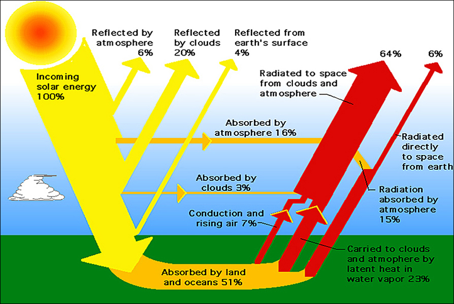
The average amount of the sun's radiation that penetrates the atmosphere and reaches the earth is 51% of the total incoming energy as illustrated above. Of the 49% that does not reach the earth, 30% is reflected back into space and 19% is absorbed by the atmosphere and clouds. The total solar energy absorbed by Earth's atmosphere, oceans and land masses is approximately 3,850,000 exajoules (EJ) per year. The earth's energy use by mankind is approximately 500 exajoules per year. This is about 0.01% of the total yearly energy coming from the sun. Putting this in another way, the earth absorbs more energy in one hour than the world uses in one year according to physicist Steven Chu, US Energy Secretary and former Director of Lawrence Berkeley National Laboratory. In total, the sun emits about 2.2 billion times the amount of radiation that is received by the earth. See the Energy Profiles Page for more general energy information. Top
World Solar Radiation Map
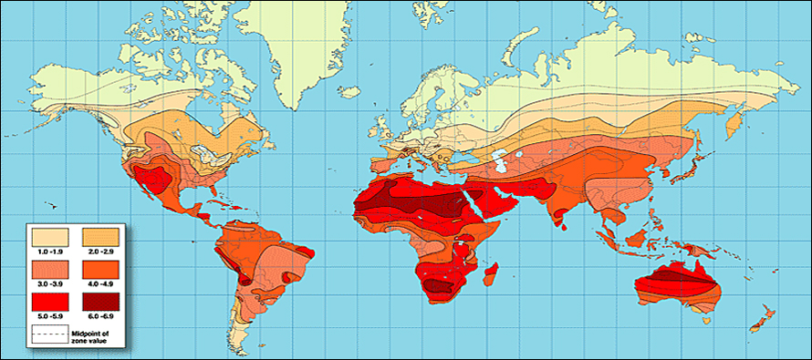
The map above shows in maroon, red, and dark orange the prime regions of the world for generating solar electricity. There are enough strong solar regions to one day provide all the energy that is needed by mankind.
Solar Radiation Spectrum
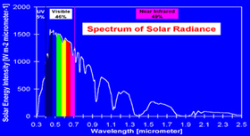
Shown in the diagram on the left is how the energy from the sun is distributed by wavelength and photon energy. As one can see, a good portion of the sun's radiation is in the visible range (46%). Radiation in the UV (ultraviolet) region (5%), which is not visible, causes the skin to tan and has more energy than that in the visible region. Radiation in the infrared region (49%), which we feel as heat, has slightly more total energy than the radiation in the visible region.
The shape of the spectrum is almost a perfect fit for a heavenly body whose temperature is 5,800 K. This is how we know with good accuracy the temperature at the sun's surface.
Other stars have enormous sources of energy in the form of high energy X-rays, but lucky for us, our sun releases almost half of its energy as visible light.
Solar Insolation
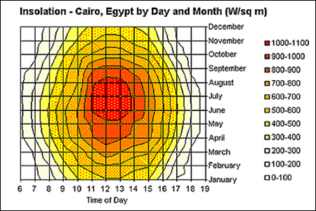
What is the difference between radiance and insolation? To a lay persn, they are probably the same thing. To a scientist, there is a distinct difference. Radiation is usually short for electromagnetic radiation and radiance is an instantaneous measurement at a distinct point in time. Solar radiation "emits" from the sun equally in all directions at frequencies that are visible and non-visable. On the other hand "insolation" is the amount of radiation "received" on a given surface (usually a square meter) on a plane perpendicular to the sun in a given amount of time (usually a day). The name comes from a combination of the words "incident solar radiation".
Over the course of a year the average solar "radiance" arriving at the top of the earth's atmosphere is 1,367 watts per square meter - called the "solar constant". The solar constant varies by up to ±3% per day as the earth orbits the sun. Because of losses in the atmosphere (about 50%), different angles to the sun from the equator to the poles (averages 50%), and no sunlight during nightime (another 50%), the average "daily insolation" for the average position on earth (ignoring clouds) is about 170 watts per square meter (one-eigth the solar constant). However, insolation varies quite at bit from place to place. Typical values are about 200 W/m^2 in Australia, 185 W/m^2 in the United States and 105 W/m^2 in the United Kingdom. Shown in the figure above is the insolation by time of day and month of the year for Cairo, Egypt. Cairo has approximately the same latitude and weather pattern as does Phoenix, Arizona. It demonstrates how an "average" daily insolation can be misleading considering winter and summer extremes. Top
All About Silicon
The Silicon Atom
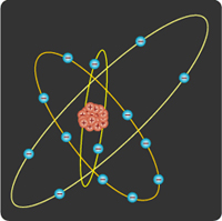
Silicon (Si) is a very abundant non-metallic element which makes up about 26% of the earth's crust and is the the second most abundant element after oxygen. It is also the 7th most common element in the universe. Silicon is usually found in the form of silicon dioxide, usually known as quartz.
As depicted in the diagram at left, the silicon atom has 14 electrons. Electrons that are further from the nucleus have more energy than electrons closer to the nucleus. The four electrons that orbit the nucleus in the outermost energy levels, valence electrons, are the ones that interact with neighboring atoms to form solids.
In silicon solids, each silicon atom shares one of its four valence electrons with each of four neighboring atoms. Only the outermost four electrons can be given to, accepted from, or shared with other atoms. These valence electrons, play a very important role in the photovoltaic (PV) effect.
The Silicon Lattice
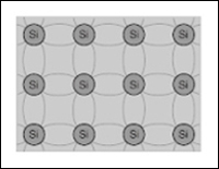
Large numbers of silicon atoms bond with each other by means of their valence electrons to form a crystal. Shown at the left is a simplified two dimensional picture of silicon crystal. The actual crystal is a more complicated three dimensional structure.
Silicon crystal consists of "units of five silicon atoms" - the original atom plus the four other atoms with which it shares valence electrons. This repeated atom pattern is known as the silicon lattice. Pure silicon is a very poor conductor of electricity, but when certain impurities are added (called "doping") its electrical characteristics are greatly enhanced. Hence the name "semiconductor".
Under certain conditions silicon conducts electricity and under other circumstances it doesn't. Solar cells using this technology are referred to as crystalline silicon cells.
Creating Silicon Wafers
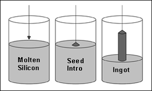
Almost all of the silicon crystals grown for solar cells are produced by the Czochralski process shown at the left (invented in 1916 by the Polish chemist Jan Czochralski, pronounced Cho-crawl-ski). Very high purity, 99.9999% pure, semiconductor grade silicon (a few parts per million of impurities) is required for solar applications.
The process begins when the production chamber is heated to approximately 1500 degrees Celsius to melt raw silicon in a crucible. Small precise amounts of impurity atoms such as boron or phosphorus are added to the molten silicon in order to dope the silicon, changing it into n-type or p-type silicon.
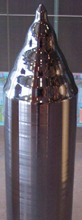
When the silicon is fully melted, a small precisely oriented seed crystal mounted on the end of a rotating shaft is slowly lowered until it just dips below the surface of the red hot molten silicon. The shaft rotates counter clockwise and the crucible rotates clockwise. The rotating rod is then drawn upwards very slowly, allowing an ingot to be formed. By precisely controlling the temperature gradient, rate of pulling, and speed of rotation, a large, "single crystal", cylindrical ingot is extracted from the melt, as shown on the right.
The ingot can be one to two meters in length depending on the amount of silicon in the crucible. This process is normally performed in an inert atmosphere, such as argon, and in an inert chamber. A cutting machine designed to slice very hard silicon uses a multi-wire diamond saw. This device is especially important in the silicon solar cell industry in order to cut the ingots into very thin wafers 200 microns (millionths of a meter) or so thick, and some as thin as 160 microns.
These extremely thin wafers are very brittle and are easily broken. Extreme care is necessary in the handling of these wafers to prevent damage. Top
Crystalline Silicon Solar Cells
The Photovoltaic Effect
The PhotoVoltaic (PV) effect is the process by which a PV cell converts sunlight into electricity. When light shines on a PV cell, the radiation may be reflected, absorbed, or passed right through. But only the absorbed light generates electricity. The energy of the absorbed light is transferred to electrons in the atoms of the PV cell. With their newfound energy, these electrons escape from their normal positions in the atoms of the semiconductor material and become part of the electrical flow, or current, in an electrical circuit. A special electrical property of a PV cell - called the "built-in electric field" - provides the force, or voltage, needed to drive the current through an external load, such as a light bulb.
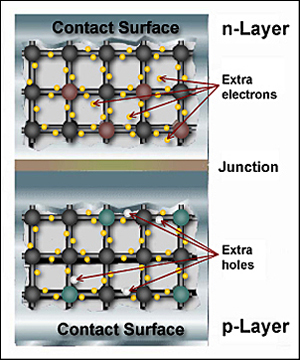
To induce the "built-in electric field" within a PV cell, two layers of differing silicon are placed in contact with one another. One layer is an "n-type" material with an abundance of electrons, which have a negative electrical charge. The other layer is a "p-type" material with an abundance of "holes," which have a positive electrical charge. The top layer is "doped" with phosphorus, which bonds with the silicon to create a negative charge (extra electrons). The bottom layer of the PV cell is usually "doped" with boron, which bonds with the silicon to create a positive charge (extra holes). The "dopant," which is the introduced element, has either three or five valence electrons—which is one less or one more than silicon's four. Substituting a phosphorus atom (with five valence electrons) for a silicon atom in a silicon crystal leaves an extra unbonded electron that is relatively free to move around the crystal. Substituting a boron atom (with three valence electrons) for a silicon atom in a silicon crystal leaves a hole (missing electron) that is relatively free to move around the crystal.
When n- and p-type silicon come into contact, the two semiconductors behave like a battery, creating the "built-in electric field", or voltage, at the surface where they meet called the "p/n junction". The voltage causes electrons to move towards the negative surface, where they become available to the external electrical circuit. At the same time, the holes move in the opposite direction, toward the positive surface, where they await incoming electrons. When the sun's photons enter the semiconductor, some of the the photons with the "right amount" of energy collide with atoms and free negative electrons and free positive holes are created. The "right amount" of energy is called the "band gap" energy and it varies from one semiconductor material to another. Given the electric field, the free negative electrons go in one direction and the free positive holes go in the other creating a current of electricity. The p/n junction is the key instrument in the creation of electricity by a solar cell. For more detailed descriptions of the above see the Junctions & Band Gaps Page.
Crystalline Silicon Cell Structure
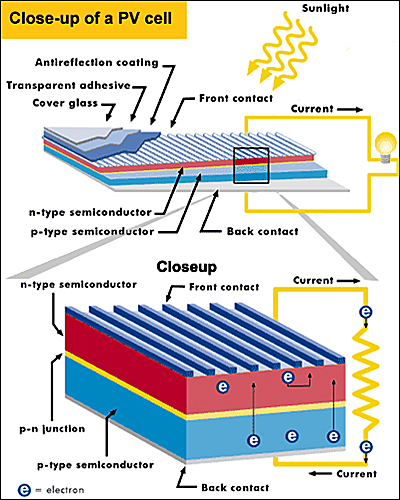
A typical solar cell consists of a glass or plastic cover, an anti-reflective layer, a front contact to allow electrons to enter a circuit, a back contact to allow them to complete the circuit, and the semiconductor layers where the electrons begin and complete their journey.
The most important parts of a solar cell are the semiconductor layers. This is where electrons are freed and the electric current is created - it's the active layer. When sunlight enters the cell, its energy knocks electrons loose in both layers. Because of the opposite charges of the layers, the electrons want to flow from the n-type layer to the p-type layer, but the electric field at the P-N junction prevents this from happening. The presence of an external circuit provides the escape path for electrons in the n-type layer to travel to the p-type layer. Extremely thin wires running along the top of the n-type layer provide the external circuit and the electrons flowing through this circuit provide the current.
Because the amount of power produced by a single solar cell is relatively small, one to two watts, designers group solar cells together to form modules (panels) that supply a more useful level of voltage, current, and power. Solar cells may be connected in series to produce higher voltages. This is done by connecting the positive terminal of one cell to the negative terminal of the next cell. Cells may also be connected in parallel to produce more current. This is done by connecting the positive terminal of the first cell to the positive terminal of the next cell, and the negative terminal of the first cell to the negative terminal of the second cell. This kind of solar cell is called a crystalline silicon cell. They are the dominant technology in the solar marketplace, accounting for about 90% of the installed market at the end of 2011. Efficiency of crystalline solar cells range from about 15% to a high of 23% which is very, very good. See Solar Efficiency Limits page. Efficiency is defined as the electrical energy converted by the cell compared to the energy of the sunlight striking the surface of the cell. Top
Houses On The Grid
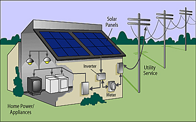
A house is said to be "on the grid" if in addition to having solar panels installed it is also still connected to the local electricity "grid" from the local power company. Homes on the grid do not normally have battery storage, instead they draw power from the grid during evenings and very cloudy days, When they are drawing power from the grid their meters operate normally and they pay the normal price for their electrical service. If during daylight hours their solar system is generating more electricity than they are using, their meter runs backwards and they pump electricity back into the grid for others to use. When their meter runs backwards, they are selling electricity back to their local power company at the same price that they buy it. Residential solar systems have become very popular in Arizona. Currently (Q4 2011) demand exceeds supply and the incentive budget of the State is forecast to be overrun. This has caused the state government to reduce the per residence incentive in order to stretch the budget. Top
Utility Systems
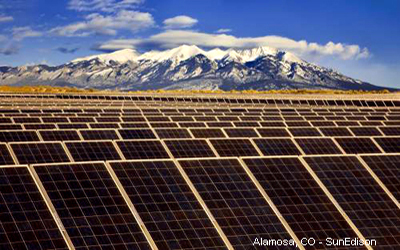
Utility use of solar power differs completely from residential use. As the picture on the left of Alamosa, CO by SunEdison indicates, a large amount of land is required to "house" the incredible amount of panel arrays necessary to generate electricity on a scale to compete with other sources of energy such as coal, gas, and nuclear reactors. On the other hand, solar electrical systems are relatively easy to build compared to alternatives. It takes a year or so to construct a "solar field" as opposed to several years to build a coal or gas fired plant and ten years to bring a nuclear facility on line.
Although decreasing, subsidies from government agencies are still necessary to make utility solar systems competitive. Why would government agencies subsidize solar power? Because solar power (like wind) is carbon free and is a very "green" source of power. Although nuclear power is also carbon free, disposing of the waste uranium is a major problem. If solar electricity can be generated on massive scales (like other energy sources), costs will continue to come down and become competitive without subsidies. Solar power is forecast to be competitve with coal without subsidies by the year 2014. Solar power is very popular with conservationists and most government agencies. See Solar Costs for a more detailed cost discussion. Top
Thin Film Solar Cells

Some newer types of solar cells are made from thin films of semiconductors chemically vapor deposited (CVD) or sputtered on glass or metal. However, thin film cells are not as efficient as silicon cells. The semiconductor materials in a thin film cell are just a few microns (millionths of a meter) thick, whereas crystalline silicon cells are 100 times or more thicker. If the wavelength of incoming light is longer than the thickness of the cell, it most likely will not be absorbed. This means that wavelengths in the infrared part of the spectrum will be weakly absorbed. Hence, thin film cells convert only 8 to 12% of incoming light versus 15 to 23% compared to crystalline silicon cells. But, thin film cells are considerably cheaper to make because they use only 1 or 2 percent of the expensive semiconductor material of a crystalline silicon cell. This is a huge advantage in system cost. Because deposition systems can deposit materials on large surfaces, modules (panels) are made of much larger cells, typically about 2 feet by 4 feet and only one cell per panel. These panels are fairly robust and can operate in a wide temperature range and in a variety of light conditions, including dawn and dusk. Because thin film panels are less efficient, more are required to generate a given amount of electricity. Hence space is a consideration in the decision as to which technology is chosen.
Cadmium Telluride (CdTe)
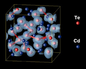
The most significant vendor using thin film cadmium telluride technology is First Solar, the largest manufacturer of solar modules in the world, headquartered in Tempe, Arizona. First Solar has come on very strong since 2006 due to its low module manufacturing cost per watt ($.73 as of Q4 2011). First Solar had about 7% of world market share as measured by watts installed during 2011. Another company making CdTe solar panels is Abound Solar located in Loveland, Colorado.
Cadmium telluride (pictured on the left) is a semiconductor which is made from cadmium and tellurium. In general, the PV principles of converting light into electrical energy are the same as silicon cells. CdTe modules are in the range of 12% to 14% efficient versus 13% to 20% for crystalline silicon modules. CdTe has an optimum absorption profile (band gap) for the light spectrum of sunshine which allows it to obtain better performance in dim lighting. On the other hand, since CdTe cells are generally not as efficient as silicon cells, CdTe requires more total surface area to produce a given amount of electricity. This translates into more land, more inverters, etc. Hence this technology is used more in the massive utility market where cost is king and land is plentiful, whereas crystalline silicon is used more in the residential and commercial roof markets where space is king.
CIGS (Copper Indium Gallium diSelenide) Cells
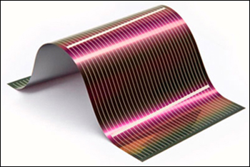
Another type of thin film solar cell is made from Copper Indium Gallium diSelenide, CIGS for short (pronounced Sigs). This is noteworthy because the semiconductor material can be deposited on a flexible base or substrate. Shown at the left is a cell from Global Solar Energy Inc. located in Tucson, Arizona. Global Solar uses stainless steel as a substrate.
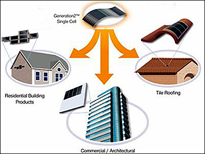
Although much smaller than the normal Cadmium Telluride market, CIGS technology is breaking into new markets in what is called the Building Integrated PhotoVoltaic (BIPV) market. Unlike conventional PV products such as solar panels, which are an add-on to say a roof, BIPV is manufactured directly into building materials, such as roof shingles, and installed during the building's construction stage.
With PV solar cells built right into walls, roof and glass, the building material itself is able to generate the electricity needed to sustain the building’s needs. This is indeed a new exciting breakthrough for solar electricity.
CIGS cells have a better efficiency than other thin film technologies by about 2%. Every 1% of efficiency represents about a 6% overall cost reduction due to less land, modules, inverters, labor, etc. So a 2% efficiency lead would be about a 12% cost savings, not insignificant. CIGS also employs low cost deposition methods that are an alternative to expensive vacuum deposition processes. CIGS solar cells are expected to pass cadmium telluride in efficiency. In theory, both CIGS and CdTe solar cells can achieve a maximum efficiency of about 30 %. In real world terms however, CIGS is expected to come out on top. A more practical real life best industry efficiency is expected to be about 25%.
Computing giant IBM announced a deal with Japanese semiconductor equipment manufacturer, Tokyo Ohka Kogyo (TOK) to make thin-film solar cells from CIGS. Neither IBM nor TOK plan to manufacture the solar cells themselves, rather, they are developing technology that will be licensed to solar manufacturing companies.
IBM's CIGS technology came out of its Research Division and they believe that it can achieve 15% efficiency in production. IBM's manufacturing process calls for the chemicals to be dissolved in a liquid and then dried. It does not require a vacuum, does not require as much energy to run as standard CIGS techniques, and is a faster process. Top
Solar Efficiency Limits
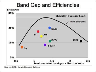
The maximum theoretical efficiency of a perfect solar cell using a p/n junction to extract electrical power was first calculated by William Shockley and Hans Queisser in 1961 It is now known as the Shockley Queisser (SQ) Limit. A solar cell's energy conversion efficiency is the percentage of power converted from sunlight to electrical energy under "standard test conditions" (STC). The STC conditions approximate solar noon at the spring and autumn equinoxes in the continental United States with the surface of the solar cell perpendicular to the sun. The modern SQ Limit calculation is a maximum efficiency of 33% for any type of single junction solar cell. The original calculation by Shockley and Queisser was 30% for a silicon solar cell. Current maximum theoretical solar cell efficiencies vary by the band gap of the semiconductor material used for the p/n junction as shown on the left (see P/N Junction and Band Gaps page). The best modern production silicon cell efficiency is 23% at the cell level and 20% at the module level as presented by SunPower in May, 2010. In the laboratory, the record solar cell efficiency for monocrystalline silicon is held by the University Of New South Wales in Sydney, Australia at 25%.
There are a number of assumptions associated with the SQ Limit that restrict its general applicability to all types of solar cells. Although there are numerous programs underway to find ways around the SQ Limit, it is still applicable to 99.9% of the solar cells on the market today. The critical assumptions are:
- One semiconductor material (excluding doping materials) per solar cell.
- One P/N junction per solar cell..
- The sunlight is not concentrated - a "one sun" source.
- All energy is converted to heat from photons greater than the band gap.
For a more detailed discussion of efficiency see the Solar Efficiency Limits page. Top
Sun "Tracker" Arrays
Shown at the left are single axis "tracker" modules at Nellis Air Force Base in Nevada, USA. The "tilted" arrays were designed and built by SunPower Corporation of San Jose California.
The arrays are tilted 20 degrees back from the vertical position. Tracker tilt angles reduce the wind profile and decrease the elevated end’s height off the ground.
Tilted single axis trackers typically have the face of the module oriented parallel to the axis of rotation. As a module tracks the sun, it sweeps a cylinder that is rotationally symmetric around the axis of rotation.
Notice the shading in the photograph. Field layouts must consider shading from one panel to the one behind it and to the ones adjacent to it. The spacing has to be optimized considering the amount and cost of land versus any shading losses.
The figure to the left shows a typical sample of power generated over the course of a day. The red line shows the power curve generated by fixed panels. The yellow is for trackers. The dotted black line is the typical power load during the summertime in California on a scale to the right. The green line shows the peak summer load at 5:00 in the afternoon with air conditioners still running at the office and also at home.
On average, a tracker system will generate 30% more power than a fixed system. However, at the peak time of day when utilities are taxed the most, trackers generate 40% more power and at this particular time of day, power is worth much more in the marketplace than the average daily price. From actual test data, SunPower maintains that the benefits of the increased harvest of electric power far exceeds the extra costs of the motor, mounting items, and control systems of the tracker. Top
Solar Inverters
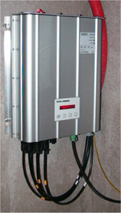
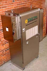
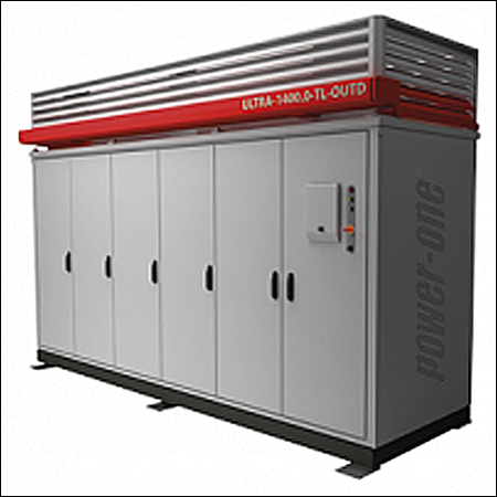
Solar panels produce direct current (DC). Almost all customer devices use alternating current (AC). The main function of an inverter is to convert DC into AC. There are two types of inverters: those that are tied to the grid and those that are stand alone inverters. We shall be discussing only inverters that tie into the grid. Inverters come in a large array of sizes from a home inverter shown on the left, to a commercial inverter on the right, to a utility size mega-watt inverter shown below.
Homes and businesses that have a grid tied solar system sell the excess electricity that they generate back to the utility. This is known as "net-metering". The entity that owns the solar equipment receives compensation from the utility for the outflow of power. For example if during a month, a solar power system feeds 500 kilowatt-hours into the grid and uses 950 kilowatt-hours (approximately the national average) from the grid. It would only owe 450 kilowatt-hours worth to the utility. A two-way meter is required for net metering. In essence when excess solar power is generated, the inverter feeds the grid through the meter, which runs backwards selling the power back to the utility at the same price as it is purchased. Net-metering policies vary somewhat from state to state. Inverters do not provide backup power during power outages. For safety reasons if the grid has lost utility power, the inverter will automatically shut down to prevent the current it produces from harming workers who are sent to restore power.
Solar inverters perform three major functions: as mentioned above they convert the current from DC to AC, they ensure that the solar current and voltage are synchronized with the grid, and they perform Maximum Power Point Tracking (MPPT). Inverters take the DC power from the solar string (typically 300 to 600 volts DC) and invert it to AC power so it can be fed into the grid. The inverter synchronizes its frequency with that of the grid (e.g. 60 cycles) using a local oscillator.
It must also match the voltage to the grid voltage. The inverter's AC phase angle must be within 1 degree of the power grids AC. The inverter has an on board computer which will sense the grid's AC current waveform, and output a voltage to correspond exactly to the grid's. The Power-One inverter shown on the left supports utility scale grid installations.
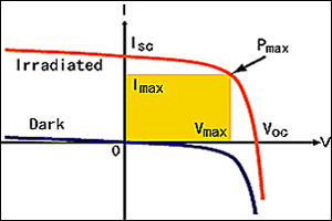
MPPT - Solar inverters include MPPT (Maximum Power Point Tracking) that enables the inverter to extract an optimal amount of power from the solar string by calculating the array's Maximum Power Point (MPP). Each string of solar panels will have its own MPP. MPPT seeks the "unique current" that the inverter will draw from the string in order to optimize power output (power equals voltage times current).
In the graph pictured on the left below, V-max is determined by the relatively constant string voltage (the goal is 600 volts - the maximum allowed in the US). I-max is calculated by the inverter to output P-max - the MPP. To find the point where the string produces maximum power, the inverter uses a trial and error algorithm adjusting the current it intakes in one direction and then another. If the power increases, it keeps going in that direction. If the power decreases, it reverses its direction. This is a dynamic situation as the string voltage can vary over time, such as when a cloud obstructs the sun's radiance.
Each inverter has a Peak Power Tracking Voltage rating. This represents the DC voltage "range" in which the inverters' MPPT will operate. The installation designer must configure the strings so that during most of the year the voltage of the strings is within the Peak Power Tracking Voltage range. This can be a challenging task as string voltages can fluctuate as much as 35% as a result of swings in ambient temperature.
Efficiency - Most inverters have efficiencies between 94%, and 98%. The energy lost during inversion is converted into heat. For an inverter to output its rated amount of power, it will need to have power input that exceeds the rated output. For example, a 5,000W rated inverter operating at 95% efficiency will need to consume 5,263 watts (rated power of 5,000 divided by 95%) from the string.
Anti-islanding protection - Normally, solar inverters will shut off if they do not detect the presence of the grid. If however, there are circuits in the electrical system that happen to resonate at the frequency of the grid, the inverter may be fooled into thinking that the grid is still active even though it has been shut down. This is called "islanding". An inverter designed for grid operation will have anti-islanding protection built in. It will inject small pulses that are slightly out of phase into the AC system in order to cancel any stray resonances that may be present after the grid has shut down. If it does not detect any signal, it will then shut itself down. For more information on a central inverter company, see Power-One on the Companies Page.
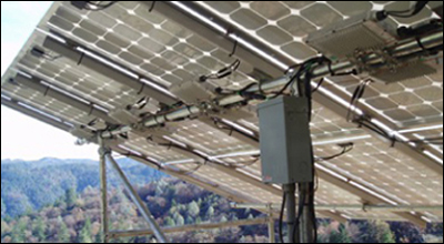
Micro inverters address some of the challenges associated with central inverters. Micro inverters are placed on each solar panel as opposed to one central location. See four light tan boxes on each panel at the left (ignore dark gray box). A "distributed" inverter approach reduces the negative effect of dust, debris, and cloud shade on any one array or on several arrays. With a centralized inverter controlling a whole string of modules (typically 17 or so), if one module or several modules are performing significantly below the the others (strings are performance matched during installation), the power output of the whole string is reduced. With micro inverters, solar modules are installed in "parallel" with only an AC connection (no DC), so issues with any one module will not affect the rest of the array. The solar array is no longer subject to the "Christmas Light Effect" because it no longer has a single point of failure. As a result, micro inverters do "harvest" more energy than central inverters.. However, in total micro inverters also cost more. Micro inverter companies say the increased cost is more than worth it and have made significant inroads into small to medium sized systems. Another micro inverter advantage is remote real time tracking ability. Since each module has an inverter which contains communication electronics, it is possible for maintenance purposes to see exactly how each panel is performing on a remote customer computer. For more information on micro-inverters, see the Enphase Energy Section on the Companies Page. Top
Central Inverters vs. Micro Inverters
There is some friendly controversy between large inverter companies and micro inverter companies. Some people use the analogy that the micro inverter entrance is akin to the PC revolution in the computer industry. This may or may not be true. Some of the micro inverter advantages in smaller installations do not hold true in utility size operations. Here are the advantages of central inverters:
- Central inverters are less expensive than micro inverters in total.
- Higher transmission voltages are more efficient than lower voltages, have a cost advantage, and most utility electricity is already moved this way.
- Central inverters are better at interfacing and monitoring negative events on the grid.
- Utility and large commercial centers are out in the open and shading (except for cloud cover) is not an issue.
- Utilities are already very sophisticated in the management of their sites and tracking as many as 50,000 thousand individual micro inverters on a 10 MW site is not practical.
- The large commercial and utility markets are forecast to grow faster than the residential market.
Micro inverters perform the same basic electrical functions as their big brothers, but do it for each panel rather than the whole solar array. Here are the advantages of micro inverters:
- Micro inverters do harvest more electricity, estimated to range from 5% to 20%.
- Micro inverters output AC current directly from each panel, so there is no need for DC wiring, etc. Installer electricians and their companies like AC which they are very familiar with in most of their normal applications.
- There is no single point of failure in a micro inverter system. An inverter failure affects only a tiny fraction of the system.
- Voltages are only 240 volts AC which are much safer for technicians than 600 volts DC, plus the whole system can be shut down for repairs. A central system is "live" and dangerous as long as the sun is shinning.
- Micro inverters are much more flexible when it comes to roofs with shading, east and west slopes, odd shapes, etc.
- Large micro inverter systems do not require a huge enclosure with a concrete pad, large cooling fans, and isolation for safety's sake.
- Data collection systems down to the panel level are very advantageous from a maintenance point of view to medium size commercial customers.
So we can see that each type of converter has significant advantages depending on the customer. Utilities and large industrial customers will gravitate to central inverters. Residential, small commercial customers and local installers will like the micro inverter. As of Decembe, 2011 the largest micro inverter installation was one mega-watt in size. Most likely in the future, micro inverters and big central inverters will both prosper in their respective territories. Top
Laboratory Technology Advances:
There are some interesting things happening in universities around the world that may eventually find their way into solar cell production. Here are a few examples:
Australian National University - Plasmonic Particles
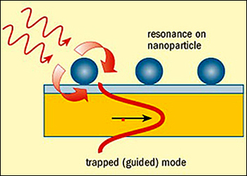
Kylie Catchpole, from the Australian National University (ANU) in Canberra, discovered that silver nanoparticles 100 nanometers (billionths of a meter) in size that are deposited on the "surface" of thin film silicon solar cells do not reflect light that has fallen on them as one would expect. Instead the light is bounced back and forth within the cell allowing longer wavelengths to be absorbed due to the plasmonic effect. (The plasmonic effect is the oscillation of electrons in a solid stimulated by incident light. Resonance occurs when the frequency of the light photons matches the natural frequency of the surface electrons.) The light comes in, gets scattered by the nanoparticle, and then is absorbed by the solar cell. The light is not absorbed by the silver nanoparticle. The nanoparticles on the surface do not affect the workings of the solar cell below, they just increase the absorption.
The sketch at the left shows long wavelengths of light striking small silver metal nanoparticles on the surface of thin film silicon only several microns (1 micron = one millionth of a meter) thick. The long wavelengths are then absorbed by the silicon below as opposed to passing through the silicon as is the case for normal thin film silicon. These experimental silver coated solar cells produce 30% more electricity than conventional thin film silicon cells because of the absorption of the long wavelengths of light. Processes now have to be developed to be able to mass produce the experimental cells commercially. Commercial solar cells using this technology are expected in about three years. For more information on this technology see Nanoparticles Inspire Plasmonic Solar Cells. Top
National Renewable Energy Laboratory (NREL) - Plasmonic Particles
The NREL in Boulder, Colorado is using Quantum Dots (QDs) to generate more than one electron-hole pair for every photon absorbed. See the QD photo from MIT at the left. However the NREL's QDs are "inside" the solar cell as opposed to being on the surface (as at ANU above). No solar cells produced prior to December, 2011 have quantum efficiencies greater than 100 percent. Quantum efficiency (not to be confused with solar cell efficiency) per the NREL is the “ratio of collected charge carriers (electrons or electron holes) to incident photons”. In layman terms - its the ratio of the number of electrons produced in a solar cell to the number of the sun's photons hitting the cell.
Researchers from the NREL have demonstrated quantum efficiencies of 114 percent in solar cells “excited” from photons from the high-energy region of the solar spectrum. That is from the near ultraviolet through the visible light spectrum, 0.3 to 0.7 micrometers (millionths of a meter). See the solar radiation chart above. Energy is always conserved. The extra electrons come from the extra energy left over after the initial photon-electron collision. Light photons with wavelengths below 0.7 micrometers do not have enough energy to dislodge more than one electron.
NREL achieved this result with a layered quantum dot "experimental cell" composed of a surface of anti-reflective glass, a thin layer of semiconductor zinc oxide “textured” at the nano level, a QD layer of lead selenide doped with ethanedithol (a bonding agent) and hydrazine (a deposition stabilizer), and a thin layer of gold for the collector electrode.
This process, which creates more than one electron-hole pair from a single photon, is called "multiple exciton generation" (MEG) by NREL. However, it should be emphasized that the research into Quantum Dots is at a very basic stage of demonstrating scientific principles. No one at this time has actually made a pre-production Quantum Dot solar cell. Production solar cells using Quantum Dots are thought to be about 10 years into the future. See NREL News Release for MEG.
California Institute Of Technology - Nanoparticle Wires
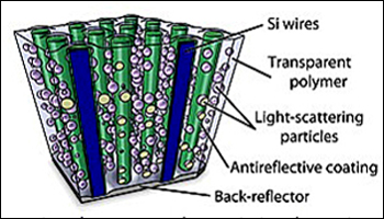
Harry Atwater and fellow researchers at Caltech have developed arrays of minute silicon micro wires - 1 micron in diameter and up to 100 microns high - that are embedded in a thin transparent rubbery polymer that absorbs enough sunlight to have a potential efficiency of 15 to 20%, as good as the best crystalline cells of today. See Solar Efficiency Limits page.
While these arrays have the thickness of a conventional crystalline solar cell, their semiconductor volume is equivalent to that of a two micron thick film. These solar cells use only about two percent as much silicon as their big brothers. The transparent polymer contains reflective nanoparticles of aluminum that shuttle light back and forth in the cell until it is finally absorbed by a tiny wire of silicon. The experimental arrays are on the order of a few square centimeters in size. To be commercially viable, these cells have to be scaled up by a factor of a 100 times or more. One feature of this technology is that the final solar cell is very flexible which opens up new solar BIPV markets as shown above in the CIGS section. For more information on this technology see Caltech Researchers Create Highly Absorbing Solar Cells. Top
Stanford University - Photon Enhanced Thermionic Emission (PETE)
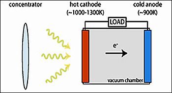
A conventional thermionic converter (used on satellites) is driven solely by intense heat (1,500°C) and converts thermal energy into electricity. The converter consists of two electrodes separated by a vacuum. When the cathode is heated to a high temperature, electrons become excited, jump across the thin vacuum to the relatively cold anode, and drive a current through an external circuit back to the cathode. The Stanford Photon Enhanced Thermionic Emission (PETE) prototype uses concentrated sunlight as its source of energy and in a two step process uses both the sun's photon energy and its heat to excite the cathode electrons to jump across the vacuum to the collector anode. The cathode emitter is a semiconductor material rather than a metal electrode. First the sunlight's photons partially excite the electrons in the cathode semiconductor (similar to a silicon PV cell) so that in step two the remaining heat energy necessary for emission is lower than that for a standard thermionic converter (but not as low as a regular solar cell). The surface of the cathode on the vacuum side is texturized to increase emissions. PETE converts about 25% of the sunlight's energy into electricity.at 200°C and higher efficiencies at higher temperatures, i.e. 45% at 1000°C. However, not all the heat is consumed, the surplus heat can be used to feed an auxiliary heat engine. Coupling a PETE device with a thermal heat engine such as a parabolic solar trough system, which already has a steam turbine engine (see Parabolic Trough Systems), the total energy efficiency could be in the 50% to 60% range - a major improvement over current solar technologies. See Solar Efficiency Limits page. This technology would not be used on roof top systems because of the extreme temperatures. But think of a solar front end concentrating the sunlight, a PETE conversion station, and a back end parabolic trough/steam turbine generator. This type of hybrid solar system could be used by utilities to generate grid electricity. That is the "vision". A lot of work needs to be done to get from today's laboratory set up to a production product in the field. A competitive product is probably 8 to 10 years away. For more information on this technology see PETE 2010 Progress Report. Top
MIT - Can Solar Energy Be Economically Stored?
Solar power has two major issues that have been holding back wide spread acceptance of the technology: 1) the initial capital equipment cost is expensive relative to other alternatives, and 2) solar power is a daytime phenomenon. In the first case, the cost of PV solar has come down rapidly and has reached "parity" with other alternatives. In the second case, storage of solar power in batteries is very expensive and not enough capacity exists, the same as other alternatives. Daniel Nocera, Professor of Chemistry and Energy at MIT, and assistant, Matthew Kanan Postdoctoral Fellow, have made a scientific discovery that may lead to a cheap way to store solar energy in the future.
Water is H2O - two hydrogen atoms and an oxygen atom. Scientists have known for for a long time how to use electricity to split water into hydrogen and oxygen, which is called electrolysis. The new discovery is a way of doing what existing electrolyzers do, but much more simply and efficiently. The key component in the process is a new catalyst which consists of cobalt metal, phosphate and an electrode. Running a small electric current through the water, the water's oxygen atoms bubble up, leaving pure hydrogen in the water. Another separate catalyst recovers the hydrogen gas. Pure hydrogen, is an excellent way to store energy. See Eureka Moment video!
The oxygen and hydrogen gases can be stored in separate containers. At a later time, the oxygen and hydrogen gases can then be fed into a fuel cell, creating carbon-free electricity. (Fuel cells combine two gases, usually hydrogen and oxygen, to make electricity.) In the MIT lab, electricity came from the grid, but the electricity could come from solar panels, or for that matter, from wind turbines or hydropower. This system imitates the water splitting reaction that occurs in nature that is called photosynthesis (carbon dioxide + water + light => stored sugar + waste oxygen). For more information on this technology see New Water Splitting Catalyst Found.
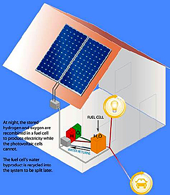
Dan Nocera's vision for the future is that each residential house will have a PV solar panel system on the roof. During the day the sun will generate electricity and the excess, that is not currently used for heat, air conditioning, etc., will be converted to hydrogen and oxygen gas using only ordinary water and stored in local tanks. When needed, the hydrogen and oxygen gas will be fed into a fuel cell to generate electricity at night or on cloudy days. The electricity could be used for home appliances or to charge an electric car or anything else. The fuel cell by-product is again water which would be fed back into the water tank. Most likely a connection to the grid would be maintained for back up purposes. See Dr. Nocera video.
This vision is probably ten plus years away. Still it is important for scientists to have a road map to the future to guide them in their day to day activities along the way. Dr. Nocera has founded a new start up company in the Boston area, Sun Catalytix Corporation, thanks to a $700,000 seed investment led by Polaris Ventures. That might sound like a small sum, but Nocera has been an epic center of buzz ever since he first published the research behind Sun Catalytix. There are still several major problems to be solved: Sun Catalytix needs to replace the platinum used in the "other electrode" in Nocera's hydrogen process with something cheaper. (Platinum is not cheap.) Also the large scale processes for manufacturing need to be worked out. Sun Catalytix recently received a contract for over $4 million in federal funding from the US Department of Energy (DOE). DOE selected Sun Catalytix as one of only 37 recipients from over 3,600 applicants for the first round of funding for transformational energy technologies. In October, 2010 Sun Catalytix raised $9.7 million in a second round of financing lead by Tata Limited. Sun Catalytix Web Site
There is competition, Nanoptek Corporation, also in the Boston suburbs, is pursuing its own catalytic, water-splitting process, and has raised $4.7 million in financing. For now, both companies are in stealth mode, refusing press inquiries. Their goals are obvious: A cheap way to get energy from the sun, just like plants do. Nanoptek Web Site Top
Space Based Solar Power (SBSP)
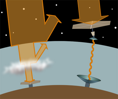
The ultimate solar power station is in outer space. As shown in the sketch at the far left, there are energy losses as the sun's rays are reflected from the atmosphere, clouds, dust, the day-night cycle and seasonal changes. Only about 50% of the sun's energy reaches the earth and then only 15% to 25% of that reaches the grid. As shown on the right hand side of the sketch, a Space Based Solar Power (SBSP) system would collect solar energy by a satellite 24 hours a day, convert it to microwaves, transmit the microwave radiation to earth where it would be captured by a very large ground antenna and converted into usable electricity on the grid. The energy efficiency from the space station to the grid would be about 50%, roughly the same as fossil fuel electrical plants.
The SBSP concept was first published in November 1968 by Dr. Peter Glaser. In 1973 he was granted a U.S. patent for his method of transmitting power from a satellite using microwaves sent from a large antenna to a combination rectifier-antenna, now called a "rectenna" on the ground.
NASA began to study the concept in 1974. They found that the concept had several major problems - the huge expense of putting the solar satellite in orbit requiring hundreds of space trips and the lack of experience in space for projects of this scale. The proposal showed enough promise to merit further research. Research has continued to this day.
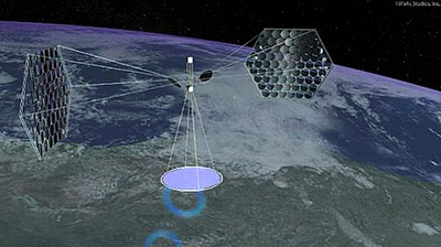
There have been enormous improvements in solar panel efficiency. Research has continued to this day. There have been enormous improvements in solar panel efficiency reducing the size of the panel array in space. (See an artist's sketch of a proposed satellite system at the left.) Rocketry has also improved, but not sufficiently enough that "hundreds of transport trips" can be undertaken cost effectively at this time. Satellite transportation costs remain the biggest obsticle to this technology being implemented. Many noted scientists believe that if the US "concentrated" on this effort, the costs of transporting the spacecraft materials to space would come down and the whole project would be cost competitive with fossil fuels.
As we come to the later part of the 21st century and with the availability of fossil fuels declining resulting in extremely high fuel prices, many scientists believe SBSP will be seen as the ultimate answer. The real question is "Will we by then be ready to exploit this endless source of cheap electrical power?" For a more detailed discussion of SBSP see the Solar High Brochure by Dr. Philip Chapman former NASA Astronaut, Physics Professor at MIT, and Employee of Dr. Peter Glaser.
Ohio University has initiated a "SunSat Design Competition" which is "an international competition intended to accelerate the design, manufacture, launch and operation of the next generation satellites that will collect energy in space and deliver it to earth as electricity. The Mission of the SunSat Design Initiative is to move space solar power out of the research labs and onto the public agenda. This will be done by virtual story telling and networking on a global basis, explaining what space solar power is and how and why it will become the ultimate renewable energy resource for Planet Earth." See the Ohio University SunSat Design Competition.
For a very interesting NASA video featuring a commentary by Dr. Peter Glaser himself click here.
Top